Look at the panel with buttons on left of the work field. By default, "Hand" is selected — in this mode, you can move and select existing objects.
For add new objects to the scheme, select the desired type and then left-click on the places where you want to create objects of the selected type.
For create a pipe, select the node to which first end of the pipe should be connected, and then click the middle mouse button (click on the wheel) on the second node. A pipe will be laid between them. You can select one or several objects at once — after clicking on the second node, as many pipes will be laid as objects have been selected.
If the mouse does not have a wheel (for example, it is not a mouse, but a laptop touchpad), instead of the middle button, right-click on node and select "Lay pipe here".
You can delete objects by selecting them and pressing the Delete button on the keyboard. You can also right-click on the selected objects and select "Delete".
For select one object, left-click on it. You can select several objects by dragging the mouse cursor with the left button pressed on the work field.
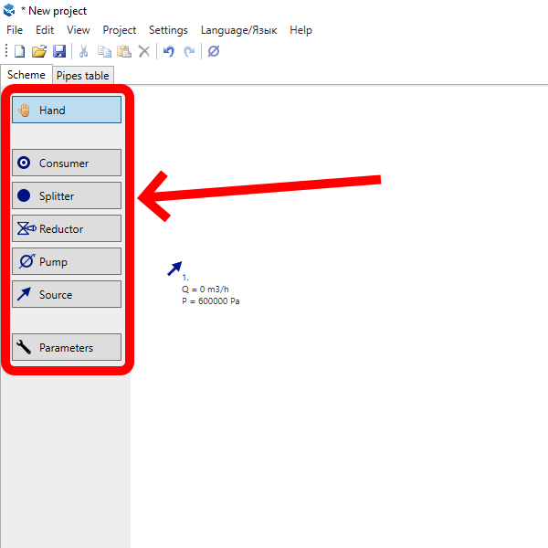
There are six types of objects in the Stokes: five types of nodes (consumers, splitters, reductors, pumps, sources) and pipes, which connects nodes.
To open the window for editing object parameters, double-click on it with the left mouse button.
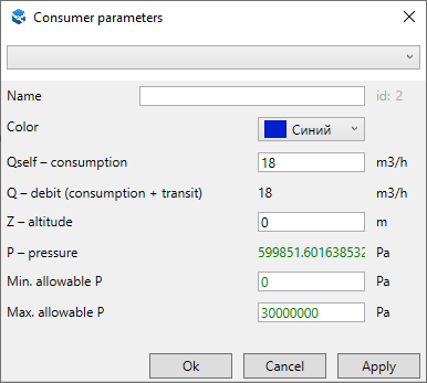
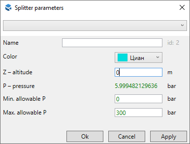
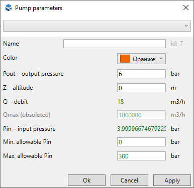
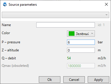
All types of objects have parameters Name and Color. These parameters are used exclusively for display on the scheme and do not affect the calculations in any way.
The object id is displayed to the right of the name. All objects have different id. You can always find the desired object by its id. To do this, press Ctrl+G and enter the id of the object you are interested in. It will be selected, and the working area will be positioned so that the desired object is in the middle of the scren
In the upper part of the parameters window for all types of objects there is a drop-down list that allows you to quickly set some parameters with some typical values.
The final consumer of gas/liquid.
The branching point of the pipeline.
Nodes that change the pressure to a given level. They differ only in the icon, otherwise they work the same way.
The calculation model assumes that reductors and pumps can provide unlimited gas/liquid flow and their outlet pressure remains fixed.
Source gas/liquid. This is usually the connection point to the main pipeline.
The calculation model assumes that sources can provide unlimited gas/liquid flow and their outlet pressure remains fixed.
For more information about λ, ζ and ∆P, see formulas for calculating pressure losses on a pipeline section.

In version 22.12, a form for mass editing of objects was added. You can edit either all the objects in the scheme at once, or only the selected ones. The parameters are set individually for each type of object.
You can open the mass editing form in the menu Edit → Mass editing of objects F2. If any objects were selected at the moment of opening the form, the "What to edit" switch will be set to "Selected objects only". But you can also choose the option "All objects".
Specificities of form fields

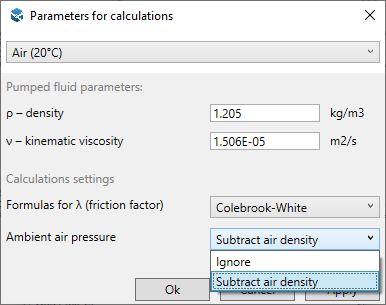
For configure the scheme parameters click the "Parameters" button on the left side of the window, under the object type buttons.
Attention! By default, the parameters for natural gas are used. If you are calculating not a gas pipelines, be sure to change the viscosity and density of the pumped fluid!
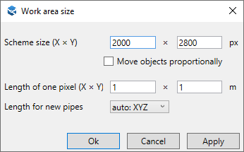
By default, work area size is 2000x2800 pixels. You can change it by pressing Ctrl+R or click Project → Work area size in main menu.
If the checkbox "Move objects proportionally" is checked, then when changing the size of the scheme, all objects will move proportionally closer/away from each other. If there was a background image, it will also increase, so that the objects will remain in the same places relative to the background.
If the checkbox is not checked, the working area will be enlarged/reduced, but the objects will be at the same distance from each other as before.
If you started to make a scheme and at some point realized that it turns out too tightly, the labels of objects are crawling over each other, try to increase the size of the scheme 2-3 times with the checkbox pressed.
If you add a background image Ctrl+Shift+B, the resolution of which is greater than the current size of the scheme, the working field will be automatically enlarged to the size of the image.
The "Length of one pixel" fields usually do not need to be changed in this window. It is more convenient to set the scale by clicking the "recalc scale" checkbox in the pipe parameters window (see video on 2:37 in article about automatic pipe length).