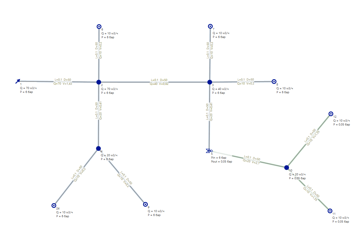
For example, the following scheme will be used:
You can download example stks-file, open it in Stokes and change different parameters there. There are 25 objects in the file – the free version of Stokes is enough.
If there are pumps or reductors in the scheme, then the network is divided into separate subnets, which are calculated separately. In the example above, there are two subnets:
In Stokes, pipes of different subnets are tinted with shadows of different colors. In this case, it is blue for the first subnet and light green for the second.
Flows are set as input data in properties of consumers (the Q parameter). For other objects, the initial value of the flow through them is 0.
Before starting hydraulic calculations, it is necessary to put the flow values through all nodes and pipes. To do this, the program passes from each consumer in turn to the source of the corresponding subnet and adds the consumption value of this consumer to them.
This algorithm does not try to figure out whether the diameter of pipe is enough to pump such an amount of gas/liquid through it. It's just supposed to be enough :)
When all the flows are determined, there is a passage in the opposite direction – from the source towards the consumers. In this passage, the pressure losses in the pipes is calculated:
P2 = P1 - ∆PL - ∆PZ
где
P2 – pressure at the end of pipe;
P1 – pressure at the start of pipe;
∆PL – pressure loss along length;
∆PZ – pressure change due to the altitude difference of the beginning and end of pipe.
Equations for calculation ∆PL and ∆PZ can be found in the article about formulas.
If P1 - ∆PL - ∆PZ < -101325 Pa (which corresponds to zero absolute pressure – vacuum), then P2 is set to -101325 Pa. All subsequent pipes and nodes will also have pressure of -101325 Pa.
If you see such pressure values, it means that the pipe capacity was not enough for the specified flow rate. It is necessary to increase the diameters of some pipes, or reduce consumptions of consumers, or increase the source pressure.
When the flows and pressures are calculated, Stokes checks whether the calculated parameters do not exceed the permissible values. The limits of acceptable values are set in the object parameters, these are:
If some parameters go beyond the allowed limits, the object is highlighted in red. It looks like this:


