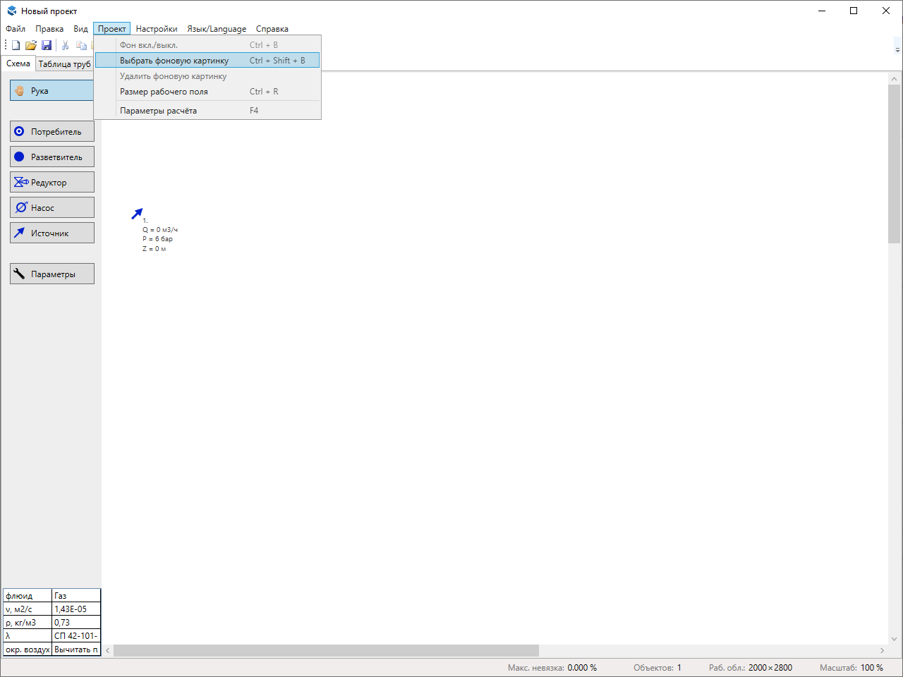
When opening the program, only one source is present in the scheme.
Usually, you start by setting up a background image. You can use any image in raster format (png, jpeg, bmp) as a background. A common option is to use a terrain plan exported to a picture from a dwg, or a screenshot from Google Maps. For convenience, you can make the background image lighter in any graphics editor that you are more familiar with.
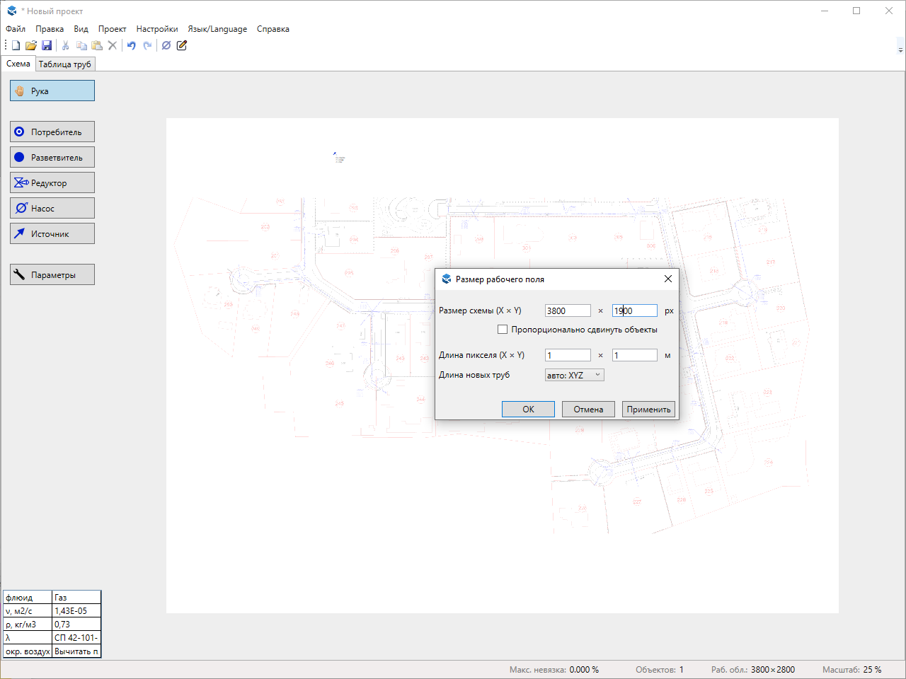
You can change the size of the workspace. When you add a background, the workarea size automatically increases to the size of the image if there is not enough space on one axis. You usually do not need to manually adjust the pixel length; it is easier to automatically recalculate the scale when you edit the pipe length (see below).
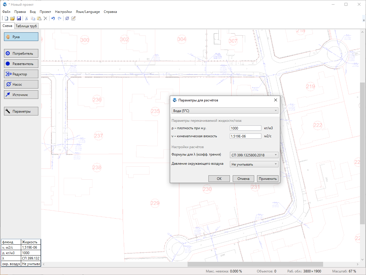
Also, don't forget to change the parameters of the pumped fluid. By default, the project parameters set the density and viscosity for natural gas (typical parameters often found in the literature). In the parameters window at the top, there is a drop-down list with several options for parameters for some gases and water at different temperatures. However, you can also calculate pipelines that pump other gases or liquids by manually entering their density and viscosity.
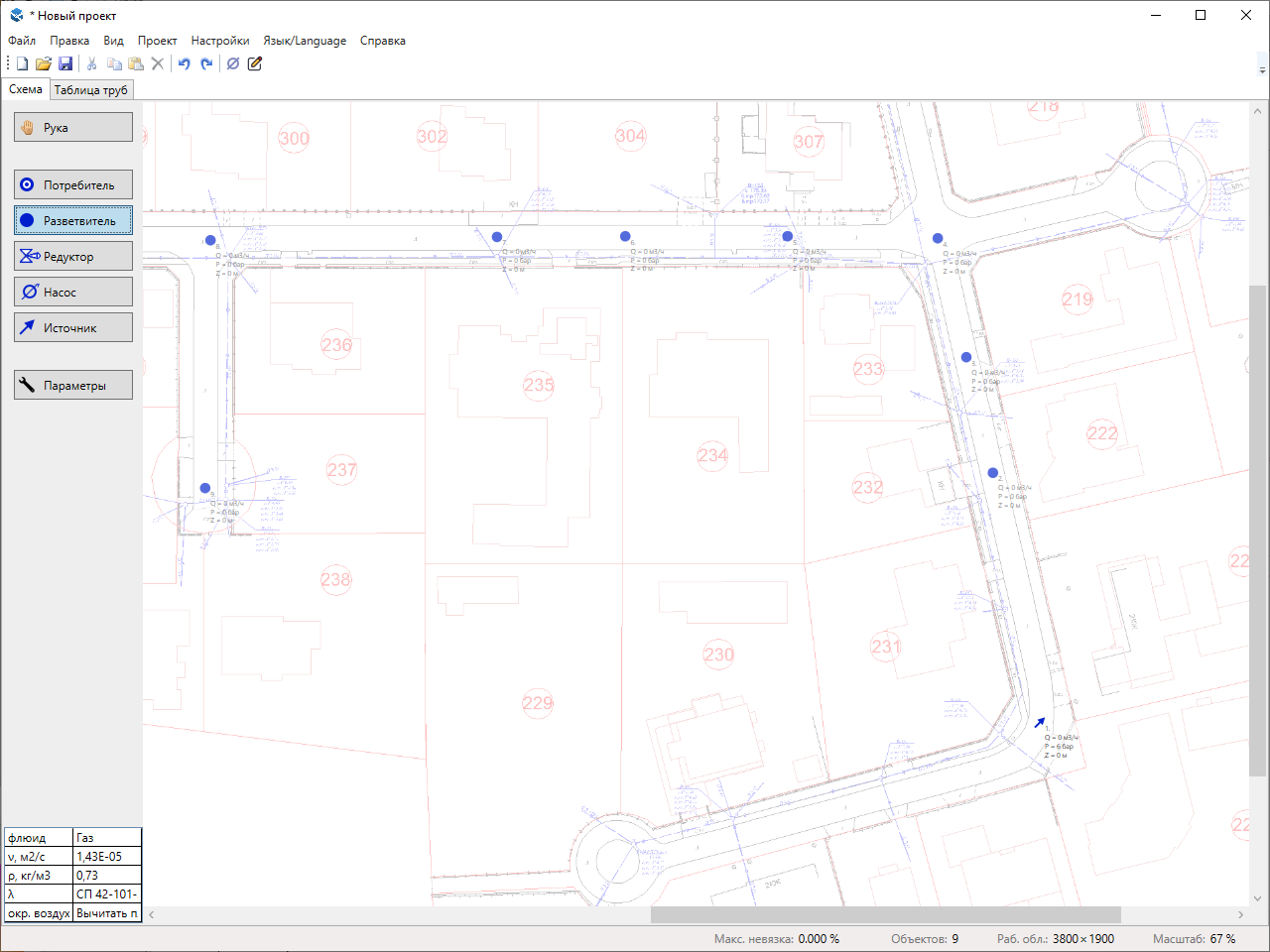
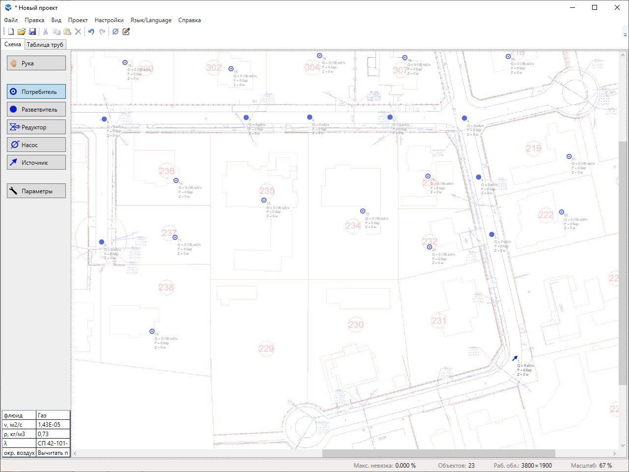
Now you need to place the node objects on the scheme. To do this, click the button with the desired object type (consumer/branching/gearbox/pump/source) on the left. Then, use the left mouse button to click on the locations where you want to place the objects of this type.
Sources, consumers, and splitter are commonly used. Reductors and pumps are only used when you need to divide the network into multiple sections with different pressures.
At this stage, it's usually more convenient to simply quickly tap on the map, leaving the objects with their default parameters. You can adjust their parameters later.
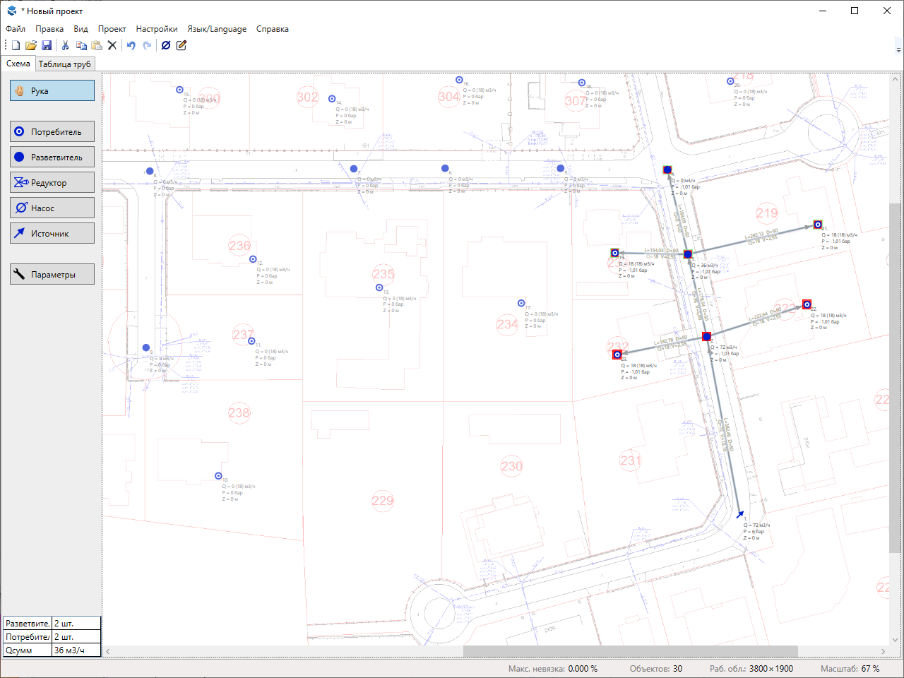

Select one or more objects. Then, click the middle button (the mouse wheel) on the object to which you want to connect the selected objects.
If your mouse doesn't have a wheel (for example, if it's a laptop touchpad instead of a mouse), right-click on the second object and select "Lay pipe here" from the drop-down menu.
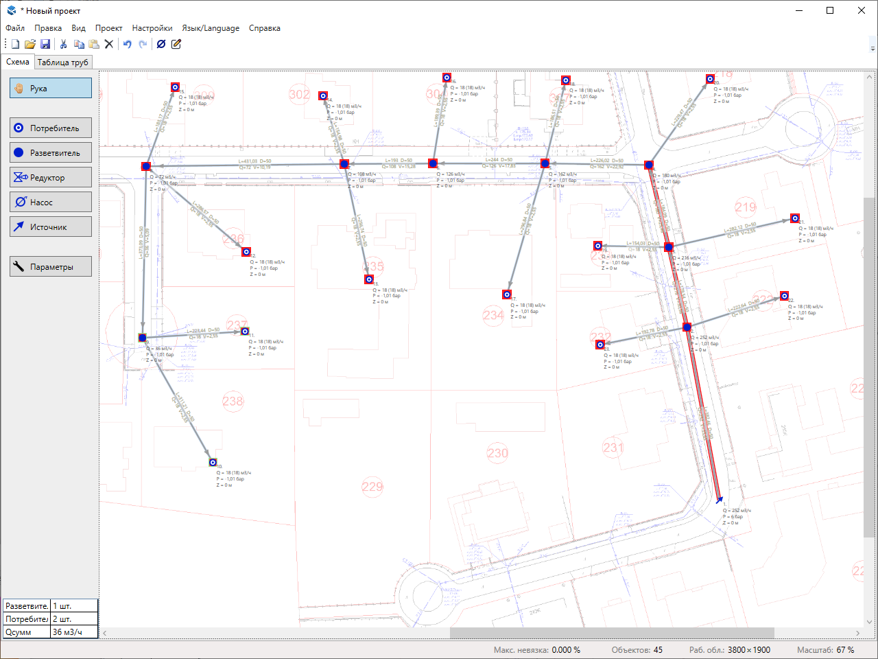
Hydraulic calculation is automatically performed each time you add/remove pipes With default parameters, it often happens that the pressure is not enough and objects are highlighted in red. At this stage, it is more convenient to quickly lay all the pipes with default parameters first, ignoring the errors that occur. It is more convenient to edit their parameters when the whole scheme is built.
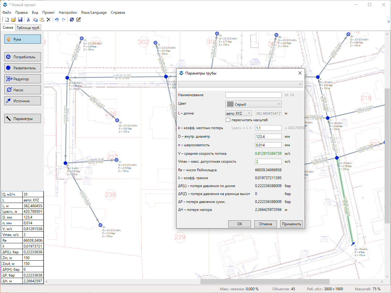
Pipe lengths are calculated automatically by default based on the set scale. You don't need to manually calculate how many meters are in each pixel of your project. Once all the pipes have been laid, double-click one of them. In the parameters window that opens, check the "recalc scale" checkbox. The length field will become active. Enter the actual length of this section of the pipeline and save. The rest will be recalculated automatically, and all new pipes will be created with the correct length. In some cases, it can be useful to fix pipe lengths. For more information, see the video about automatic pipe length. The automatic pipe lengths option was introduced in version 24.09.1; previously, only fixed length was available.
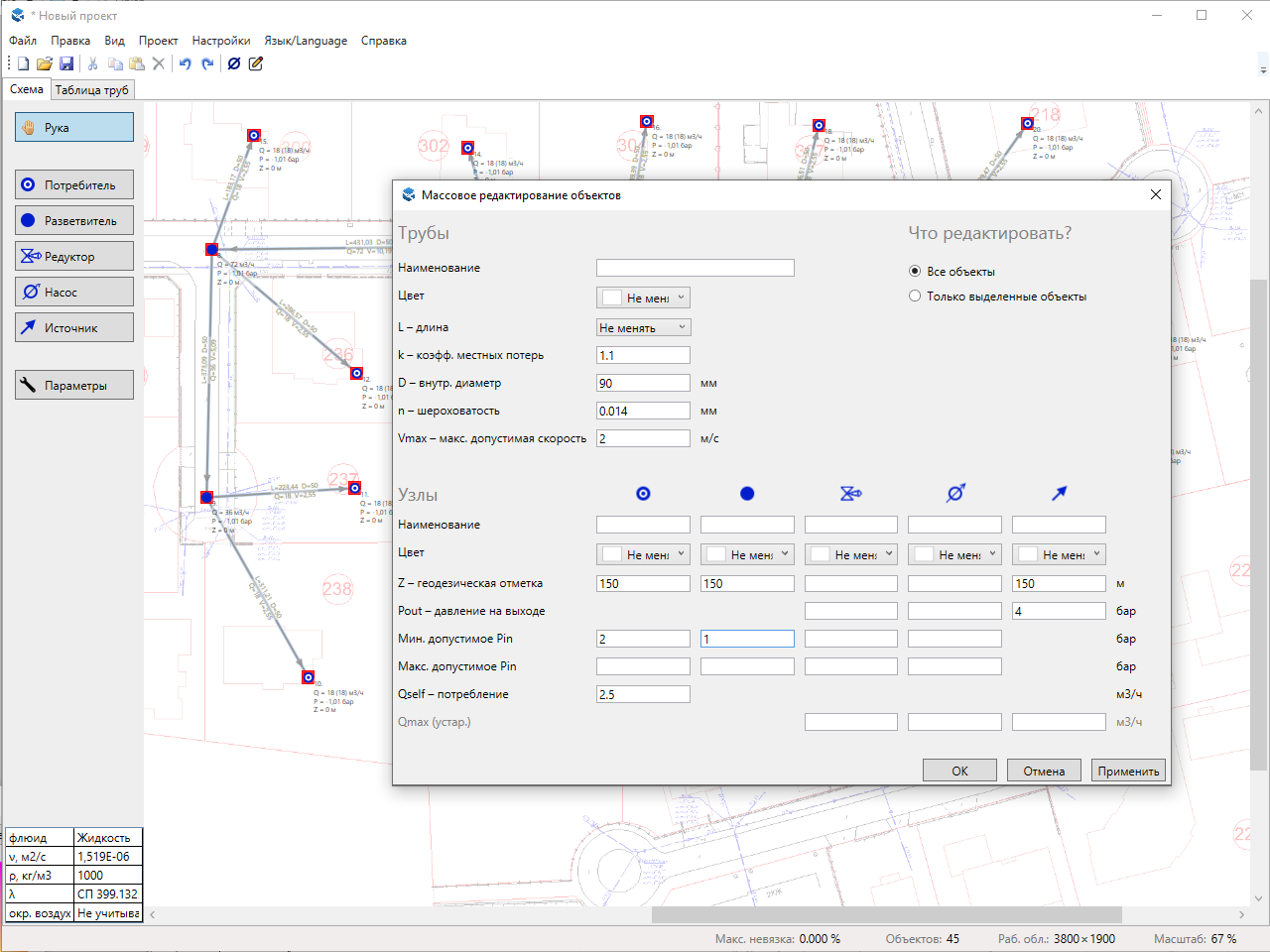
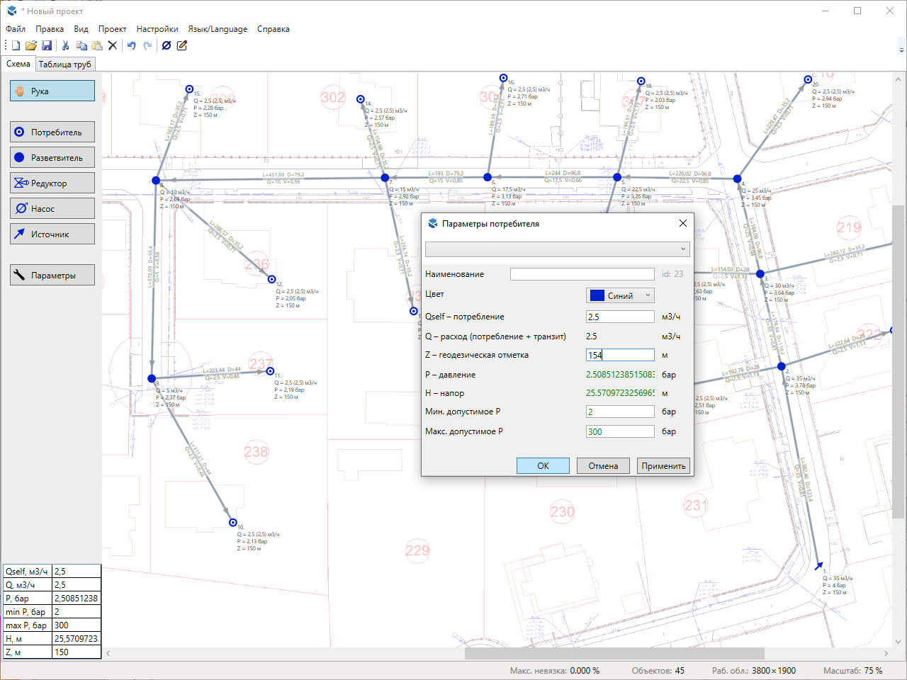
At this stage, you can start editing the object parameters. To open the object parameters window, double-click on the object with the left mouse button. In all such windows, there is a drop-down list of pre-installed options at the top. This list is most relevant for pipes, but there are fewer options for other object types.
It is more convenient to start editing parameters with mass editing. For example, if you have all polyethylene pipes, assign a roughness of 0.007 mm to all of them (or 0.014 if you coalculate the water supply). If you have most of the D110 SDR11 pipes, assign an inner diameter of 90 mm to all of them, and then change the diameters of the other sections individually.
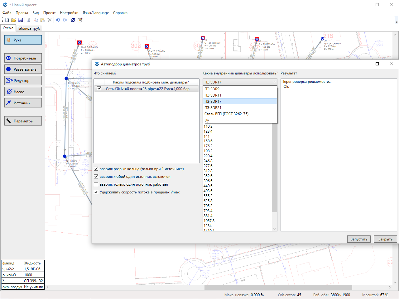
If your task is to determine the pipe diameters, then after setting the node parameters, run the autoselect of diameters. The autoselect is designed to provide a reference point. After the autoselect, you can adjust the section diameters to make them more convenient for actual pipeline installation.
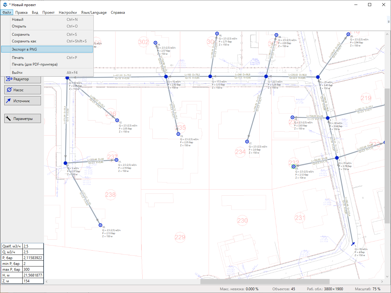
Once the calculation is complete, you can save the resulting scheme as a png image.
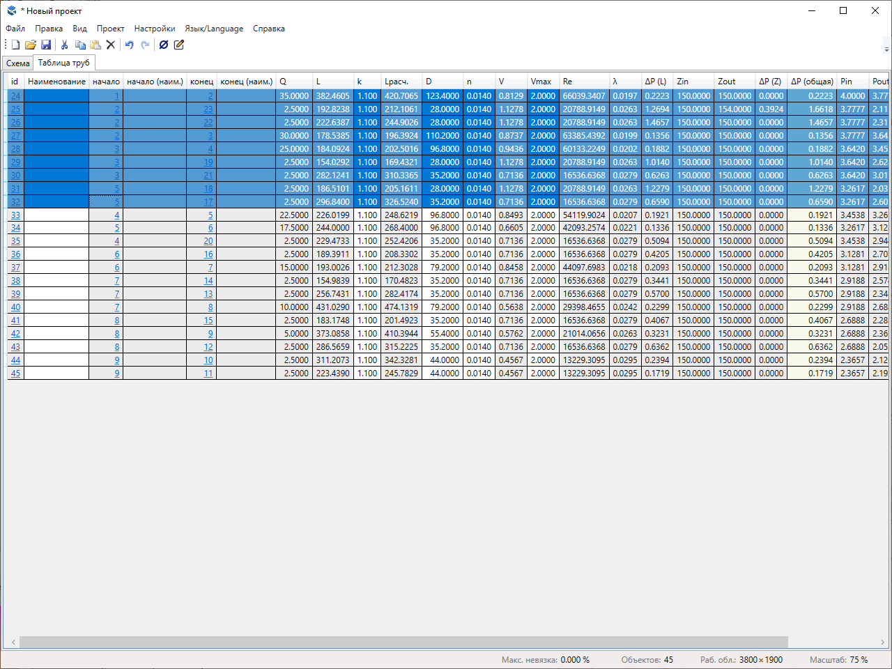
You can also copy the calculated parameters of pipeline sections to insert them in Word or Excel and edit them there. To do this, switch to the pipes table, select all Ctrl+A, copy Ctrl+C, paste Ctrl+V in the application you need, and delete the unnecessary columns there. For more information, see the help section about export.

